ENR 1.5 Holding, Approach and Departure Procedures
1 CIVIL
The holding, approach and departure procedures in use are based on those contained in ICAO Doc 8168.
1.1 Categories of Aircraft
Aircraft performance has a direct effect on the airspace and visibility needed to perform the various manoeuvres associated with the conduct of instrument approach procedures. The most significant performance factor is aircraft speed. Accordingly, the following five categories of typical aircraft have been established, based on 1.3 times stall speed Vso or 1.23 times stall speed Vslg in the landing configuration at maximum certificated landing mass (if both Vso and Vslg are available, the higher resulting value is applied), to provide a standardized basis for relating aircraft manoeuvrability to specific instrument approach procedures:
- CAT A: less than 91 KIAS;
- CAT B: 91 KIAS or more, but less than 121 KIAS;
- CAT C: 121 KIAS or more, but less than 141 KIAS;
- CAT D: 141 KIAS or more, but less than 166 KIAS;
- CAT E: 166 KIAS or more, but less than 211 KIAS.
As indicated in § 1.3 below, a specified range of handling speeds for each category of aircraft has been assumed for use in calculating airspace and obstacle clearance requirements for each procedure.
The IAC will specify the individual categories of aircraft for which the procedure is approved. Normally, procedures will be designed to provide protected airspace and obstacle clearance for aircraft up to and including CAT D. However, where airspace requirements are critical, procedures may be restricted to lower speed categories. Alternatively, the procedure may specify a maximum IAS for a particular segment without reference to aircraft category. In any case it is essential that pilots comply with the procedures and information depicted on instrument flight charts and the appropriate flight parameters shown in § 1.3 below if the aircraft is to remain in the areas developed for obstacle clearance purposes.
1.2 Obstacle Clearance
Obstacle clearance is a primary safety consideration in the development of instrument approach procedures. The criteria used and the detailed method of calculation is covered in ICAO Doc 8168, Volume II. However, from the operational point of view it is stressed that the obstacle clearance applied in the development of each instrument approach procedure is considered to be the minimum required for an acceptable level of safety in operations.
For each individual approach procedure an obstacle clearance altitude/height (OCA/H) is calculated in the development of the procedure and published on the IAC. In the case of precision approach and circling approach procedures, an OCA/H is specified for each category of aircraft listed in § 1.1 above. OCA/H is:
- in a precision approach procedure, the lowest altitude (OCA) or alternatively the lowest height (OCH) above the elevation of the relevant runway threshold, at which a missed approach must be initiated to ensure compliance with the appropriate obstacle clearance criteria;
- in a non-precision approach procedure, the lowest altitude (OCA) or alternatively the lowest height (OCH) above aerodrome elevation or the elevation of the relevant runway threshold, if the threshold elevation is more than 7 FT below the aerodrome elevation, below which the aircraft cannot descend without infringing the appropriate obstacle clearance criteria;
- in a visual (circling) procedure, the lowest altitude (OCA) or alternatively the lowest height (OCH) above the aerodrome elevation below which an aircraft cannot descend without infringing the appropriate obstacle clearance criteria.
1.3 Speeds for Procedure Calculations in KIAS
| Aircraft CAT | Vat | Range of speeds for initial approach | Range of final approach speeds | MAX speeds for visual manoeuvring (circling) | MAX speeds for missed approach | |
|---|---|---|---|---|---|---|
| intermediate | final | |||||
| A | < 91 | 90 / 150 (110*) | 70 / 100 | 100 | 100 | 110 |
| B | 91 / 120 | 120 / 180 (140*) | 85 / 130 | 135 | 130 | 150 |
| C | 121 / 140 | 160 / 240 | 115 / 160 | 180 | 160 | 240 |
| D | 141 / 165 | 185 / 250 | 130 / 185 | 205 | 185 | 265 |
| E | 166 / 210 | 185 / 250 | 155 / 230 | 240 | 230 | 275 |
Vat: speed at THR based on 1.3 times stall speed Vso or 1.23 times stall speed Vslg in the landing configuration at maximum certificated landing mass. If both Vso and Vslg are available, the higher resulting Vat is applied. * maximum speed for reversal and racetrack procedures. | ||||||
1.4 Naming Convention for Waypoints Used in Instrument Approach Procedures
- IAF is pronounceable letter name code (except in Luxembourg);
- IF is a 5 alphanumeric name code finishing with letter “I” or a pronounceable letter name code (if operational advantage);
- FAF is a 5 alphanumeric name code finishing with letter “F”;
- Where MAPT is co-located with THR, WPT is named as “RWxx (RUNWAYdesignator)”. Otherwise the WPT is named as “MAPxx (RUNWAYdesignator)”.
1.5 Arriving Flights
Controlled flights entering and landing within a TMA will be cleared to a specified holding point and instructed to contact APP at a specified time, level or position. The terms of this clearance shall be adhered to until further instructions are received from APP. If the clearance limit is reached before further instructions have been received, holding procedure shall be carried out at the level last authorized.
Due to the limited airspace available, it is important that the approaches to the holding patterns and the holding procedures be carried out as precisely as possible. Pilots are strongly requested to inform ATC if for any reason the approach and/or holding cannot be performed as required.
| Levels | Normal conditions | Turbulence conditions |
|---|---|---|
| up to FL 140 incl | aircraft CAT A/B: 170 KIAS aircraft CAT C/D/E: 230 KIAS | aircraft CAT A/B: 170 KIAS aircraft CAT C/D/E: 280 KIAS |
| between FL 140 and FL 200 incl | 240 KIAS | 280 KIAS or M 0.8, whichever is less |
| between FL 200 and FL 340 incl | 265 KIAS | |
| above FL 340 | M 0.83 | M 0.83 |
1.6 Departing Flights
Flights departing from controlled aerodromes will receive initial ATC clearance from the local TWR. The clearance limit will normally be the aerodrome of destination.
Flights departing from non-controlled aerodromes and intending to enter controlled airspace are required to file a flight plan with the nearest ATS unit prior to departure. However, where a non-controlled aerodrome is located outside a CTR and where telephone facilities are not available, flight plans may be filed during flight. In those cases pilots should ensure that the flight plan is filed at least 10 MIN before entering controlled airspace and that RTF transmissions are kept to a minimum.
2 MILITARY
The holding, approach and departure procedures in use are designed according criteria contained in the STANAG 3759 - APATC-1(A). Procedures reviewed, changed or developed henceforth are based on the STANAG 3759 - AATCP-1(C). The STANAG 3759 and its allied publication AATCP-1, adopt ICAO Doc 8168, Volume II for procedure design. The AATCP-1 is a supplement to PANS-OPS that provides for criteria for specific military needs. Procedures developed according AATCP-1 are annotated “MIPS” (NATO military instrument procedures standardisation). More detailed explanation is available in the BEMIL FLIP (IFR). Belgian military IFR publications are also available through the CENOR website:
URL: www.cenor.org
2.1 Categories of Aircraft
Aircraft performance has a direct effect on the airspace and visibility needed to perform certain manoeuvres, such as circle to land, turning missed approach, final alignment correction to land and descent. The most significant performance factor is aircraft speed. Accordingly, the following five categories of aircraft have been established, based on 1.3 times stall speed in the landing configuration at maximum gross landing weight. The OPS authority determines the category of minima required and to be used by their aircraft.
- CAT A: less than 91 KIAS;
- CAT B: 91 KIAS or more, but less than 121 KIAS;
- CAT C: 121 KIAS or more, but less than 141 KIAS;
- CAT D: 141 KIAS or more, but less than 166 KIAS;
- CAT E: 166 KIAS or more.
2.2 Minima for Instrument Approach Procedures
Instrument approach procedure minima published in AD 2 and the BEMIL FLIP (IFR) and established in accordance with the ‘NATO Supplement to ICAO Doc 8168 - OPS/611 Volume II for the preparation of instrument approach and departure procedures (AATCP-1)’ will be applied at all Belgian military aerodromes.
The published minima for instrument approach procedures are the lowest permitted by AATCP-1 criteria. Pilots have to consult applicable directives of their respective services for aircraft model restrictions. In case of temporary changes to the instrument landing minima, a NOTAM will be published.
2.2.1 Height above Touchdown Zone Elevation (HAT) and Height above Aerodrome (HAA)
The height above touchdown zone elevation and height above aerodrome are published together with the DA and the MDA. The HAT is the height of the DA or MDA above the highest runway elevation in the first 3 000 FT of the runway, beginning at the threshold and will be published in conjunction with straight-in minima. The HAA is the height of the MDA above the published aerodrome elevation and will be published in conjunction with circling minima.
2.2.2 Decision Altitude (DA) and Minimum Descent Altitude (MDA)
In a precision approach procedure (ILS and PAR), the DA is the lowest altitude, or alternatively the HAT is the lowest height, at which a missed approach must be initiated if the required visual reference has not been established.In a non-precision approach procedure, the MDA is the lowest altitude, or alternatively the HAT is the lowest height, below which the aircraft cannot descend until the runway environment is in sight and the aircraft is in a position to descend for a normal landing.In a circling procedure, the MDA is the lowest altitude, or alternatively the HAA is the lowest height, below which the aircraft cannot descend until the runway environment is in sight and the aircraft is in a position to descend for a normal landing.
2.3 Information About The Use of Instrument Procedures Plates
2.3.1 Specifications
The lay out and the information on the MIL IFR procedures plates is according the CENOR specifications. These specifications are agreed amongst the responsible authorities of 6 NATO nations (Norway, Denmark, The Netherlands, Germany, Czech Republic and Belgium) and they are based upon the STANAG 3970.
2.3.2 Publication
The instrument procedure plates and the aerodrome lay out plates of the Belgian MIL aerodromes published in this AIP, the BEMIL FLIP(s) and the CENOR FLIPs are identical.Due to publication cycles the moment of publication a new or revised procedure plate in the CENOR FLIPs can be different from the MIL AIP and BEMIL FLIP. To assure this situation is not a safety risk the necessary NOTAM will be published in the Belgian M-series as well as in the German U-series.
2.3.3 Landing Minima
See below for the explanation of the landing minima as it is represented in the BEMIL FLIP - IFR (High and Low Instrument Approach and Departure Procedures Belgium).
Landing minima are established for six aircraft categories, determined as follow:
| CAT | APPROACH SPEED |
|---|---|
| A | Less than 91 KT |
| B | 91 KT or more but less than 121 |
| C | 121 KT or more but less than 141 |
| D | 141 KT or more but less than 166 |
| E | 166 KT or more |
| HPMA | See page IV in BEMIL FLIP - IFR |
Note 1: Speeds are based on 1.3 times the stall speed in the landing configuration at maximum gross landing weight.
Note 2: Operational authorities determine the category of minima required and to be used by their aircraft.
Standard portrayal of instrument approach minima for landing is as follows.
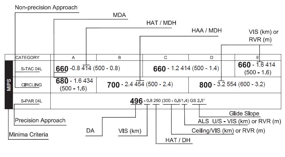
- Only “estimated horizontal visual range on ground” is available for Belgian military airfields.
- The VIS value published following the DA or the MDA is the required minimum for the approach.
- Pilots should consult applicable directives of their respective service for aircraft restrictions.
2.3.4 Procedure Design System
See below for the explanation of the procedure design system used in NATO nations that ratified the STANAG 3759 and information on the system used for Belgian civil aerodromes as well as information on the differences to fly these procedures.
2.3.4.1 Identification of Procedure Design Standards Used
Pilots should be aware of the system used for designing the procedure since it may be of influence on the way to fly the procedure.
Therefore one of the following annotations are put on the top left of the procedure plates:
- NATIONAL: Procedure designed according national specific criteria
- MIPS: Procedure designed according NATO military instrument procedures standardization implemented by AATCP-1.
- PANS-OPS: Procedure designed according ICAO Doc. 8168 Vol. II.
- TERPS: Procedure designed according NATO military criteria in APATC-1(A).
2.3.4.2 Identification of Minima Criteria
Criteria used to establish the minima are stated on the left side of the minima table (See § 2.3.3 for illustration):
- MIPS: Minima assigned according NATO military instrument procedures standardization implemented by AATCP-1.
- EU-OPS: Minima assigned according EU-OPS.
- TERPS: Minima assigned according NATO military criteria in APATC-1(A). No longer updated after 22 OCT 2008.
- NATIONAL XXX: Minima assigned according national specific criteria
2.3.4.3 ICAO (PANS-OPS) Procedures
NATO countries that have ratified STANAG 3759 will gradually recalculate their procedures according the AATCP-1 which is the ICAO PANS-OPS standard with some military exceptions and add-ons. These procedures shall be flown according STANAG 7199 and AFPP-1 covering and implementing ICAO Doc 8168 Vol I (PANS-OPS).
Note: The differences between the way of flying IFR procedures according the AFMAN 11-217 and ICAO Doc 8168 Vol I are explained in AFMAN 11-217 Vol I (Ed Oct 2010) chapter 15.
2.3.4.4 High Performance Military Aircraft Procedures
HPMA procedures introduce a new aircraft category (See also page IV in BEMIL FLIP IFR). Procedures designed exclusively for HPMA are annotated 'HPMA' before the procedure identification. The plates for such procedures are made distinctive with a hatch pattern.